Modular Cathodic Protection System KMO NGK-IPKZ-Euro
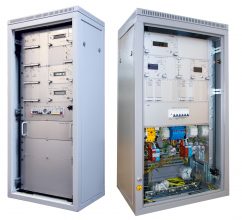
Cathodic Protection Modular Equipment System NGK-IPKZ-Euro (hereinafter – KMO) utilizes pulse converters for cathodic protection of buried steel structures from underground corrosion, logs and processes data on corrosion status and corrosion protection, transfers the data via digital interface RS-485/Fiber optic[1])/GSM1) to telemetry systems. Also, KMO NGK-IPKZ-Euro has remote measurement, remote indication, remote control and remote regulation modes. KMO meets the requirements of GOST R 51164-98, general specifications to modular cathodic protection stations and corporate Gazprom standard STO 9.4-023-2013.
Cathodic Protection Modular Equipment System NGK-IPKZ-Euro (hereinafter – KMO) utilizes pulse converters for cathodic protection of buried steel structures from underground corrosion, logs and processes data on corrosion status and corrosion protection, transfers the data via digital interface RS-485/Fiber optic[1])/GSM1) to telemetry systems. Also, KMO NGK-IPKZ-Euro has remote measurement, remote indication, remote control and remote regulation modes. KMO meets the requirements of GOST R 51164-98, general specifications to modular cathodic protection stations and corporate Gazprom standard STO 9.4-023-2013.
KMO NGK-IPKZ-Euro monitors corrosion process at one location – at a drainage point. NGK‑SKM subsystem shall be used for applications requiring more corrosion monitoring locations (up to 32).
Remote Corrosion Monitoring Subsystem NGK‑SKM may be included in the Modular Equipment System NGK‑IPKZ‑Euro or supplied separately. For more information please refer to Remote Corrosion Monitoring Subsystem’s technical documentation.
[1]) Complete equipment list is defined in accordance with the Order sheet for the equipment.
Standards compliance
The equipment is included in the register of PJSC Gazprom.
The equipment is included in the register of PJSC Transneft.
Certified in the INTERGAZCERT system.
GOST R 51164-98 “Steel main pipelines. General requirements for corrosion protection “.
GOST 9.602-2016 “Buried structures. General requirements for corrosion protection “.
Temporary requirements for modular cathodic protection stations of PJSC Gazprom.
STO Gazprom 9.4-023-2013 “Monitoring and forecasting the corrosion state of facilities and equipment. Data collection, processing and analysis system. Basic requirements”.
Equipment Capabilities
- Automatic stabilization of the cathodic protection current.
- Automatic stabilization of total or polarization potential of the protected underground steel structure.
- Automatic transfer to cathodic protection current stabilization in case of open circuit to reference electrode.
- Stabilization of output voltage (during intense testing)
- Automatic switching on of the backup converter in case of failure of the primary converter.
- Protection from pulse (atmospheric) over voltage surges for all external commutation circuits.
- Protection against external short circuits and overloads.
- Automatic recovery to operating mode after recovery of the disconnected feed.
- Measurement, local indication at the control module NGK-BU-EURO and transfer via digital interface RS-485/Fiber optic[1])/GSM13) Annex M to the telemetry system the following parameters:
- output current of cathodic protection of the converter;
- potential (total, polarization) of the protected structure at the drainage point;
- output voltage of the converter;
- converter mode of operation (current stabilization, stabilization of the total or polarization potential, stabilization of the output voltage);
- converter control mode (manual, remote);
- protection time for the structure;
- current date and time;
- uptime for primary and back up converters;
- Corrosion rate indicator (BPI-2);[2])
- data on corrosion rate and corrosion penetration from US IKP ST devices (1 to 8 indicators);
- voltage of primary and back up[3]) power supply lines ~230 V;[4])
- accumulated power consumption at primary and back up line ~230 V;16)
- operation of the primary or back up converter;
- status of power modules;
- temperature in the KMO cabinet.
- Remote control via digital interface RS-485/Fiber optic15)/GSM15) of the following converter modes:
- converter mode of operation (cathodic protection current stabilization, stabilization of the total or polarization potential, stabilization of the output voltage);
- switching on and off the converter standby mode (cathodic protection current is zero, no stabilization).
- Remote adjustment via digital interface RS-485/Fiber optic15)/GSM15) (Annex M) of the following parameters:
- output current of the converter;
- potential (total, polarization) of the structure;
- output voltage of the converter.
- Transfer of the signal on opening of the KMO cabinet door.
- Automatic switching to back up power line ~230 V, in case of power failure at the primary line15),16).
- Communication via interface RS‑485/Fiber optic (ВОЛС)15)/GSM15) with telemetry system without power supply ~230 V for 24 hours15),16).
- The following emergency signals may be transferred to the terminals of the relay port via double throw potential-free relay contacts16):
- feed line failure ~230 V
- opening of the cabinet door;
- switching off of the primary converter.
[1]) These functions may be implemented on demand in accordance with the Order sheet for KMO equipment.
[2]) Only for primary converter (SKZ1).
[3]) These functions may be implemented on demand in accordance with the Order sheet for KMO equipment.
[4]) These functions are not available for KMO NGK-IPKZ-Euro(PT).
[5]) Recommended for 4-5 kW KMO modifications, operated at high temperature locations.
[6]) Standard configuration of KMO modification that supports polling of Corrosion Indicator (IKP) indicators includes metering unit Mercury 200.02 (connected via CAN interface to the Control Module NGK-BU-Euro. This enables power consumption data transfer to Linear Telecontrol System (SLTM).
Basic Parameters and Properties
Please see Tables 1,2 for Voltage and type of current of the input power, rated output voltage, rated output power, rated total output current, power input, overall dimensions and weight of the Modular Equipment System KMO.
Energy Conversion Efficiency* of the power supply units at rated output power, %, min. 90
*Energy Conversion Efficiency of the power supply modules NGK‑BP‑Euro(PT)‑0,2(24) and NGK‑BP‑Euro(PT)‑0,2(48) at rated output power, %, min………………………………………… 85
Current output adjustment limits, % …………………………………………………………. 1 – 100
Total potential adjustment limits for protected structure with resistive component, V from minus 0.5 to minus 4.0
Polarization potential range for the protected structure without resistive component, V from minus 0.8 to minus 2
Physical telemetry interface …………………………………… RS‑485/Fiber optic[1])/GSM6)
Telemetry communication protocol ………………………………………………… Modbus RTU
Telemetry data transmission rate, bit/s……………………………………………. 9600
Designs per U1 climatic category (cabinet meets IP34 per GOST 14254‑2015 or higher) and U2 (cabinet meets IP20 per GOST 14254‑2015) per GOST 15150‑69.
[1]) Complete equipment list is defined in accordance with the Order sheet for the equipment.
Table 1 – General Properties KMO NGK‑IPKZ‑Euro
| KMO | Supplied AC Voltage, V | Rated Output Voltage [1]), В | Rated Output Power, kW | Rated Total Output Current at output voltage, A | Total power consumption [2]), kV·A | Dimensions (HWD), mm, max | Weight,[3]) kg, max | ||
| 24 V | 48 V | 96 V | |||||||
| NGK‑IPKZ‑Euro‑0.2(24)‑U2 | 150 – 264 | 24 | 0.2 | 8.0 | – | 0.25 | 1351×615×475 | 75(100) | |
| NGK‑IPKZ‑Euro‑0.2(24)‑U1 | 1665×625×632 | 95(120) | |||||||
| NGK‑IPKZ‑Euro‑0.4(24)‑U2 | 0.4 | 16.0 | 0.49 | 1351×615×475 | 78(103) | ||||
| NGK‑IPKZ‑Euro‑0.4(24)‑U1 | 1665×625×632 | 98(123) | |||||||
| NGK‑IPKZ‑Euro‑0.6(24)‑U2 | 0.6 | 24.0 | 0.74 | 1351×615×475 | 80(105) | ||||
| NGK‑IPKZ‑Euro‑0.6(24)‑U1 | 1665×625×632 | 100(125) | |||||||
| NGK‑IPKZ‑Euro‑0.8(24)‑U2 | 0.8 | 32.0 | 0.94 | 1351×615×475 | 83(108) | ||||
| NGK‑IPKZ‑Euro‑0.8(24)‑U1 | 1665×625×632 | 103(128) | |||||||
| NGK‑IPKZ‑Euro‑0.2(48)‑U2 | 48 | 0.2 | 8.0 | 4.0 | – | 0.25 | 1351×615×475 | 75(100) | |
| NGK‑IPKZ‑Euro‑0.2(48)‑U1 | 1665×625×632 | 95(120) | |||||||
| NGK‑IPKZ‑Euro‑0.4(48)‑U2 | 0.4 | 16.0 | 8.0 | 0.49 | 1351×615×475 | 78(103) | |||
| NGK‑IPKZ‑Euro‑0.4(48)‑U1 | 1665×625×632 | 98(123) | |||||||
| NGK‑IPKZ‑Euro‑0.6(48)‑U2 | 0.6 | 24.0 | 12.0 | 0.74 | 1351×615×475 | 80(105) | |||
| NGK‑IPKZ‑Euro‑0.6(48)‑U1 | 1665×625×632 | 100(125) | |||||||
| NGK‑IPKZ‑Euro‑0.8(48)‑U2 | 0.8 | 32.0 | 16.0 | 0.94 | 1351×615×475 | 83(108) | |||
| NGK‑IPKZ‑Euro‑0.8(48)‑U1 | 1665×625×632 | 103(128) | |||||||
| NGK‑IPKZ‑Euro‑1.0(48)‑U2 | 1.0 | 21.0 | 1.23 | 1484×615×475 | 80(105) | ||||
| NGK‑IPKZ‑Euro‑1.0(48)‑U1 | 1785×625×632 | 95(120) | |||||||
| NGK‑IPKZ‑Euro‑2.0(48)‑U2 | 2.0 | 42.0 | 2.47 | 1484×615×475 | 90(115) | ||||
| NGK‑IPKZ‑Euro‑2.0(48)‑U1 | 1785×625×632 | 105(130) | |||||||
| NGK‑IPKZ‑Euro‑3.0(48)‑U2 | 3.0 | 63.0 | 3.70 | 1484×615×475 | 100(125) | ||||
| NGK‑IPKZ‑Euro‑3.0(48)‑U1 | 1785×625×632 | 115(140) | |||||||
| NGK‑IPKZ‑Euro‑4.0(48)‑U2 | 4.0 | 84.0 | 4.94 | 1751×615×475 | 120(145) | ||||
| NGK‑IPKZ‑Euro‑4.0(48)‑U1 | 2055×625×632 | 135(160) | |||||||
| NGK‑IPKZ‑Euro‑5.0(48)‑U2 | 5.0 | 104.0 | 6.17 | 1751×615×475 | 130(155) | ||||
| NGK‑IPKZ‑Euro‑5.0(48)‑U1 | 2055×625×632 | 145(170) | |||||||
| NGK‑IPKZ‑Euro‑1.25(48)‑U2 | 1.25 | 26.1 | 1.54 | 1484×615×475 | 85(110) | ||||
| NGK‑IPKZ‑Euro‑1.25(48)‑U1 | 1785×625×632 | 100(125) | |||||||
| NGK‑IPKZ‑Euro‑2.5(48)‑U2 | 2.5 | 52.2 | 3.09 | 1484×615×475 | 95(120) | ||||
| NGK‑IPKZ‑Euro‑2.5(48)‑U1 | 1785×625×632 | 110(135) | |||||||
| NGK‑IPKZ‑Euro‑3.75(48)‑U2 | 3.75 | 78.3 | 4.63 | 1751×615×475 | 125(150) | ||||
| NGK‑IPKZ‑Euro‑3.75(48)‑U1 | 2055×625×632 | 140(165) | |||||||
| NGK‑IPKZ‑Euro‑1.0(96)‑U2 | 96 | 1.0 | 10.5 | 1.23 | 1484×615×475 | 80(105) | |||
| NGK‑IPKZ‑Euro‑1.0(96)‑U1 | 1785×625×632 | 95(120) | |||||||
| NGK‑IPKZ‑Euro‑2.0(96)‑U2 | 2.0 | 21.0 | 2.47 | 1484×615×475 | 90(115) | ||||
| NGK‑IPKZ‑Euro‑2.0(96)‑U1 | 1785×625×632 | 105(130) | |||||||
| NGK‑IPKZ‑Euro‑3.0(96)‑U2 | 3.0 | 31.5 | 3.70 | 1484×615×475 | 100(125) | ||||
| NGK‑IPKZ‑Euro‑3.0(96)‑U1 | 1785×625×632 | 115(140) | |||||||
| NGK‑IPKZ‑Euro‑4.0(96)‑U2 | 4.0 | 42.0 | 4.94 | 1751×615×475 | 120(145) | ||
| NGK‑IPKZ‑Euro‑4.0(96)‑U1 | 2055×625×632 | 135(160) | |||||
| NGK‑IPKZ‑Euro‑5.0(96)‑U2 | 5.0 | 52.0 | 6.17 | 1751×615×475 | 130(155) | ||
| NGK‑IPKZ‑Euro‑5.0(96)‑U1 | 2055×625×632 | 145(170) |
Table 2 – General Properties KMO NGK‑IPKZ‑Euro(PT)
| KMO | Supplied AC Voltage, V | Rated Output Voltage [4]), В | Rated Output Power, kW | Rated Total Output Current at output voltage, A | Total power consumption [5]), kV·A | Dimensions (HWD), mm, max | Weight,[6]) kg, max | |
| 24 V | 48 V | |||||||
| NGK‑IPKZ‑Euro(PT)‑0.2(24)‑U2 | 20 – 30 | 24 | 0.2 | 8.0 | – | 0.24 | 1217×615×475 | 75(100) |
| NGK‑IPKZ‑Euro(PT)‑0.2(24)‑U1 | 1525×625×632 | 95(120) | ||||||
| NGK‑IPKZ‑Euro(PT)‑0.4(24)‑U2 | 0.4 | 16.0 | 0.48 | 1217×615×475 | 78(103) | |||
| NGK‑IPKZ‑Euro(PT)‑0.4(24)‑U1 | 1525×625×632 | 98(123) | ||||||
| NGK‑IPKZ‑Euro(PT)‑0.6(24)‑U2 | 0.6 | 24.0 | 0.71 | 1217×615×475 | 80(105) | |||
| NGK‑IPKZ‑Euro(PT)‑0.6(24)‑U1 | 1525×625×632 | 100(125) | ||||||
| NGK‑IPKZ‑Euro(PT)‑0.8(24)‑U2 | 0.8 | 32.0 | 0.95 | 1217×615×475 | 83(108) | |||
| NGK‑IPKZ‑Euro(PT)‑0.8(24)‑U1 | 1525×625×632 | 103(128) | ||||||
| NGK‑IPKZ‑Euro(PT)‑0.2(48)‑U2 | 20 – 60 | 48 | 0.2 | 8.0 | 4.0 | 0.24 | 1217×615×475 | 75(100) |
| NGK‑IPKZ‑Euro(PT)‑0.2(48)‑U1 | 1525×625×632 | 95(120) | ||||||
| NGK‑IPKZ‑Euro(PT)‑0.4(48)‑U2 | 0.4 | 16.0 | 8.0 | 0.48 | 1217×615×475 | 78(103) | ||
| NGK‑IPKZ‑Euro(PT)‑0.4(48)‑U1 | 1525×625×632 | 98(123) | ||||||
| NGK‑IPKZ‑Euro(PT)‑0.6(48)‑U2 | 0.6 | 24.0 | 12.0 | 0.71 | 1217×615×475 | 80(105) | ||
| NGK‑IPKZ‑Euro(PT)‑0.6(48)‑U1 | 1525×625×632 | 100(125) | ||||||
| NGK‑IPKZ‑Euro(PT)‑0.8(48)‑U2 | 0.8 | 32.0 | 16.0 | 0.95 | 1217×615×475 | 83(108) | ||
| NGK‑IPKZ‑Euro(PT)‑0.8(48)‑U1 | 1525×625×632 | 103(128) | ||||||
[1]) If output voltage of KMO is below 1.5 V the actual output values may insignificantly vary from the set values.
[2]) Total power consumption specified is calculated for rated values only and may vary depending on mode of operation and modification of the Modular Equipment System (KMO).
[3]) In brackets is the weight of the KMO top modification, which includes NGK‑SKM with AKB BU and SKM modules.
[4]) If output voltage of KMO is below 1.5 V the actual output values may insignificantly vary from the set values.
[5]) Input Power specified is calculated for rated values only and may vary depending on mode of operation and modification of the Modular Equipment System (KMO).
[6]) In brackets is the weight of the KMO top modification, which includes NGK‑SKM with AKB BU and SKM modules.
Operating Conditions
Ambient air temperature, ºС…………………………………………………………………. minus 45 to +45
Relative humidity at t = +25 ºС, %, max …………………………………………………………………… 98
Atmospheric pressure, kPa (mm Hg) ………………………………………… 86.6 – 106.7 (630 – 800)
Example of model number description for Modular Equipment System:
KMO NGK-IPKZ-Euro(PT)-5.0(48)-U2-M32(5)1), where:
- KMO – Cathodic Protection Modular Equipment System;
- NGK – the abbreviation of the manufacturer;
- IPKZ – Cathodic Protection Pulse Converter;
- Euro– cabinet design in accordance with GOST 1-90 Type of supporting structures 482.6 mm. Panels and Racks;
- (PT) – used only for modular Equipment System with DC power supply voltage[1]).
- 0 – rated power output of the Modular Equipment System in kilowatts.
Possible configurations of the Modular Equipment System with different rated output power:
(1.0 – 1 kW; 2.0 – 2 kW; 3.0 – 3 kW; 4.0 – 4 kW; 5.0 – 5 kW;[2])
0.2 – 0.2 kW; 0.4 – 0.4 kW; 0.6 – 0.6 kW; 0.8 – 0.8 kW;[3])
1.25 – 1.25 kW; 2.5 – 2.5 kW; 3.75 – 3.75 kW; 5.0 – 5.0 kW;[4])).
- (48) – rated output voltage (24 V; 48 V; 96 V);
- U2 – climatic category design in accordance with GOST 15150-69.
Designs per U1 climatic category and installation location zoning (cabinet protection requirements per GOST 14254-2015 meet IP34 or higher) and per U2 (cabinet protection requirements meet IP20 or higher) per GOST 15150-69.
- М – (and all other parameters) are included in the model number only for Modular Equipment System (KMO) and Remote Corrosion Monitoring Subsystem (NGK-SKM) bundles.
- 32 – number of Corrosion Monitoring System devices NGK‑SKM (NGK‑KIP‑SM(IKP)‑1/50) from 1 up to 32 units.
- (5) – number of connections to a Test Station NGK‑KIP (lines) to Corrosion Monitoring Subsystem NGK‑SKM, from 1 up to 5.
[1]) Modular Equipment System may utilize either power supply unit NGK-BP-Euro(PT)-0.2(24) or NGK‑BP‑Euro(PT)‑0.2(48) with output power 200 W, see fig. A.7 ANNEX A.
[2]) Modular Equipment System use power supply unit NGK-BP-Euro-1.0(48) or NGK-BP-Euro-1.0(96) with power output 1 kW, see fig. A.1, fig. A.2 ANNEX A.
[3]) Modular Equipment System may utilize either power supply unit NGK-BP-Euro-0.2(24) or NGK-BP-Euro(PT)-0.2(24) or NGK‑BP‑Euro(PT)‑0.2(48) with output power 200 W, see fig. A.5, fig. A.6 ANNEX A.
[4]) Modular Equipment System use power supply unit NGK-BP-Euro-1.25(48) with power output 1.25 kW, see fig. A.3, fig. A.4 ANNEX A.
Паспорт КМО НГК-ИПКЗ-Евро (PDF, 0.3 Мб)
Паспорт КМО НГК-ИПКЗ-Евро(ПТ) (PDF, 0.3 Мб)
Декларации о соответствии ТР ТС 004/2011 и ТР ТС 020/2011
Сертификат соответствия ИНТЕРГАЗСЕРТ (лист 1)
Сертификат соответствия ИНТЕРГАЗСЕРТ (лист 2)
Разрешение Республики Беларусь
Схема внешних соединений КМО НГК-ИПКЗ-Евро
Схема внешних соединений КМО НГК-ИПКЗ-Евро с НГК-СКМ
Схема внешних соединений КМО НГК-ИПКЗ-Евро(ПТ) с НГК-СКМ(ПТ)
Акт экспертизы №0081004175 ТПП Саратовской области (PDF, 0,6 МБ)
|
Наименование оборудования |
Цена с НДС, руб./шт. |
|
КМО НГК‑ИПКЗ‑Евро-0,2 – 0,2 кВт |
Расчёт стоимости по карте заказа |
|
КМО НГК‑ИПКЗ‑Евро-0,4 – 0,4 кВт |
Расчёт стоимости по карте заказа |
|
КМО НГК‑ИПКЗ‑Евро-0,6 – 0,6 кВт |
Расчёт стоимости по карте заказа |
|
КМО НГК‑ИПКЗ‑Евро-0,8 – 0,8 кВт |
Расчёт стоимости по карте заказа |
|
КМО НГК‑ИПКЗ‑Евро(ПТ)-0,2 – 0,2 кВт |
Расчёт стоимости по карте заказа |
|
КМО НГК‑ИПКЗ‑Евро(ПТ)-0,4 – 0,4 кВт |
Расчёт стоимости по карте заказа |
|
КМО НГК‑ИПКЗ‑Евро(ПТ)-0,6 – 0,6 кВт |
Расчёт стоимости по карте заказа |
|
КМО НГК‑ИПКЗ‑Евро(ПТ)-0,8 – 0,8 кВт |
Расчёт стоимости по карте заказа |
|
КМО НГК‑ИПКЗ‑Евро-1,0 (48)– 1 кВт* |
Расчёт стоимости по карте заказа |
|
КМО НГК‑ИПКЗ‑Евро-1,25(48) – 1,25 кВт* |
Расчёт стоимости по карте заказа |
|
КМО НГК‑ИПКЗ‑Евро-2,0(48) – 2 кВт* |
Расчёт стоимости по карте заказа |
|
КМО НГК‑ИПКЗ‑Евро-2,5(48) – 2,5 кВт* |
Расчёт стоимости по карте заказа |
|
КМО НГК‑ИПКЗ‑Евро-3,0(48) – 3 кВт* |
Расчёт стоимости по карте заказа |
|
КМО НГК‑ИПКЗ‑Евро-3,75(48) – 3,75 кВт* |
Расчёт стоимости по карте заказа |
|
КМО НГК‑ИПКЗ‑Евро-4,0(48) – 4 кВт* |
Расчёт стоимости по карте заказа |
|
КМО НГК‑ИПКЗ‑Евро-5,0(48) – 5 кВт* |
Расчёт стоимости по карте заказа |
*** The equipment is manufactured with independent protection channels from 2 to 6.